
An Introduction to
PROFINET IO
PROFINET Unplugged
This paper presents an overview of PROFINET IO, a high-level network for industrial automation applications. Built on standard Ethernet technologies, PROFINET IO uses traditional Ethernet hardware and software to define a network that structures the task of exchanging data, alarms and diagnostics with Programmable Controllers and other automation controllers.
PROFINET IO is one of two open Ethernet standard automation “views” from Profibus International. While PROFINET IO focuses on Programmable Controller data exchange, PROFInet CBA (Component Based Automation) focuses on distributed automation systems. PROFINET CBA provides a DCOM-based system for organizing automation systems into networks of peer devices that can automatically exchange data using predefined relationships between the interfaces of the automation components. PROFINET CBA is thoroughly discussed in another paper.
PROFINET IO is very similar to Profibus on Ethernet. While Profibus uses cyclic communications to exchange data with Programmable Controllers at a maximum speed of 12Meg baud PROFINET IO uses cyclic data transfer to exchange data with Programmable Controllers over Ethernet. As with Profibus, a Programmable Controller and a device must both have a prior understanding of the data structure and meaning. In both systems data is organized as slots containing modules with the total number of I/O points for a system the sum of the I/O points for the individual modules.
A Little PROFINET IO Background
Most people who work in an office associate the term “Ethernet” with the physical cable behind their desk. This cable connects their office PC to the printers and Servers of the local network and the infinite web sites on the Internet. This cable is only the physical part of Ethernet, the media carrying Ethernet messages to your PC. On this wire are a whole series of communication protocols such as IP, the Internet Protocol; TCP, the Transmission Control Protocol; and various Microsoft protocols such as NetBEUI. This suite of protocols works well for the office environment. It allows users to share files, access printers, send email, search the Internet and perform all the other communications used in the office environment.
The needs of the factory floor are much different with some very special requirements. Instead of accessing files and printers, factory floor controllers must access data embedded in drive systems, operator workstations and I/O devices. Instead of letting a user wait while a task is being performed, factory floor data communications needs are real-time or very close to real time. Terminating the fill operation on a bottle requires much more time-precise communications than accessing the next page of an Internet site.
Traditionally, Ethernet had only limited acceptance in Industrial Automation. Until recently the expense, lack of sophisticated switches and routers and the domination of large vendors with proprietary protocols prevented the wide acceptance of Ethernet on the factory floor. Now with prices falling, PCs with inherent Ethernet capability moving in droves onto the factory floor and intelligent switches and routers, Ethernet is gaining acceptance. Only the lack of a widely accepted, flexible application layer targeted to Industrial Automation has prevented its complete acceptance.
Important PROFINET Terms
PROFINET IO, like many other networking systems, has a set of unique terminology. Table 1 contains a few of the terms commonly used when discussing PROFINET IO.
| AR | Application Relationship – The relationship between a PROFINET IO Controller and an I/O device. A PROFINET IO device can support more than one Application Relationship. |
| AP | Application Process – The application process running in the v device. PROFINET supports a default Application Processes and additional, profile specific application processes. |
| Channel | A single I/O point. A Channel can be discrete or analog. |
| Subslot | A group of one or more channels. Subslots can be real or virtual. |
| Slot | A group of one or more Subslots. Slots can be real or virtual. |
| Module | Modules are user defined components that plug into slots. Modules can be real or virtual. |
| Submodule | A component of a module that is plugged into a subslot. A submodule is real or virtual. |
| Cyclic Communications | Scheduled, repetitive communications. I/O data and alarm transfers are cyclic. |
| Acyclic Communications | Unscheduled, on demand communications. Diagnostic messages from an IO Supervisor to an I/O Device are Acyclic. |
| GSD | Generic Station Description |
| GSDML | Generic Station Description Markup Language – The file containing the XML description of the PROFINET IO device. |
| Provider Status | The Status an I/O device provides to an IO Controller with the data transferred to the Controller. |
| Consumer Status | The Status an I/O device provides to an IO Controller for the data it consumes from IO Controller. |
| RT | Real Time – The Real Time PROFINET IO Channel. I/O and Alarm Data are transferred over the RT Channel. |
PROFINET IO Benefits
PROFINET IO is a unique industrial Ethernet application layer. It offers many benefits over competing application layers including:
- High Speed Operation – The real time communication channel provides high speed message exchange by bypassing the time required to process the TCP/IP stack.
- Seamless and nearly identical Siemens S7 PLC integration to Profibus
- Support for time critical motion control applications
- Short Startup
- Distributed Intelligence
- Ease of installation
- Minimum commissioning time and engineering support
PROFINET Device Classification
PROFINET IO classifies devices into three types; IO-Controllers, IO-Devices and IO-Supervisors. IO-Controllers are devices that execute an automation program. Controllers, functionally similar to a Profibus Class 1 Master, exchange data with IO-Devices. IO-Devices are distributed sensor/actuator devices connected to the IO-Controller over Ethernet. In Profibus terms, IO-Devices are similar to Profibus slaves. IO-Supervisors are HMIs, PCs or other commissioning, monitoring or diagnostic analysis devices. These devices are similar to Class 2 Profibus Masters.
IO-Controllers map IO data from PROFINET IO devices into the process image of the controller. In Siemens S7 Programmable Controllers, I/O data, alarms and status data is mapped into the process image in much the same way it is done for Profibus devices. These data values are then available for use by the control program. IO-Controllers must support the following kinds of services:
- Cyclic Data Exchange – The exchange of data between IO-Controllers and IO-Devices.
- Acyclic Data Exchange – The exchange of Configuration and Diagnostic data
- Alarms – Alarm data exchange from an IO-Device to an IO-Controller
- Context Management – Connection processing
IO-Supervisors are used for commissioning and diagnostic data collection. IO-Supervisors can read and write internal diagnostic data associated with the PROFINET IO stack or diagnostic data provided by the application program of a device. IO-Supervisors can also read and write configuration data using special, non cyclic record data object services. These types of devices may only be used during the commissioning process or they may be used as an HMI to display diagnostic data to the end user.
A PROFINET IO system requires at least one IO-Controller and one IO-Device. Systems can be configured in various configurations; multiple IO-Controllers for a single IO-Device; single IO-Controllers for multiple IO-devices and multiple IO-Controllers with multiple IO-Devices.
PROFINET IO Network Representation
The network representation of a device is the view of the device from the network. In Modbus and Modbus TCP, devices are represented as a series of registers (16-bit integers) and coils (bits). In EtherNet/IPT and DeviceNetT devices are represented as objects. Other networks have other network configurations. In LonworksT, data is represented by a series of “data tags” that the device provides to the outside world. In every case above, the device presents some view of itself to the outside world. That representation is the network representation.
The PROFINET IO network representation is very similar to Profibus. It consists of a device with slots, subslots and channels. Subslots are subcomponents of a slot. Each subslot is assigned a number of I/O points or channels. A channel is the PROFINET IO term which refers to one physical discrete input, discrete output, analog input or analog output. A device can have almost any number of slots, subslots and channels.
Except for Slot zero, every other slot and subslot contains status, diagnostic and alarm data for the channels of that slot. For points transferred to an IO-Controller, provider status and diagnostic information is automatically transferred on every I/O scan cycle. For points transferred to an IO-device, consumer status is returned to the IO-Controller.
Even though PROFINET IO devices and GSD files refer to “Slot zero”, there is no Slot zero. The first I/O slot of a device is slot one. Instead of referring to an actual slot, Slot zero refers to the device itself. No I/O data is contained in Slot zero. In place of I/O data, Slot zero manages all the generic device data like the vendor name, product catalog number and software and hardware version information and other similar information.
Modules are specific functional components that can be associated with a slot. Modules can be virtual or real. A module, real or virtual, must be plugged into a slot before the I/O device goes online. The module gives the slot a specific identity. For example, a 16 discrete input module gives the slot a 16 discrete input identity. In the same way that modules provide identity to slots, sub-modules provide subslot identity. The 16 discrete input module can be composed of one 16 discrete input sub-module, two 8 input sub-modules or four, 4 input sub-modules.
IO-Controllers associate to a device and all the slots and subslots. The current version of PROFINET IO only supports devices associated to one IO-Controller at a time. Future versions of PROFINET IO may lift this restriction and associate to IO-Controllers by slot.
In an IO-Controller like a Siemens 317 Programmable Controller, the I/O points or channels for the subslots assigned to that Programmable Controllers is collected and that data group forms the I/O data image that is transferred between the IO Device and the IO Controller. For example, if you have a PROFINET IO device with four input slots (16 inputs each) and two output slots (16 outputs each), the I/O image transferred between the controller and device is 4 bytes in the direction of the Programmable Controller and 2 bytes in the direction of the IO Device.
Internally in an IO Controller, all PROFINET IO inputs are assigned to the Input data table and all outputs are assigned to the Output Data Table, just as is done for Profibus.
Configuring PROFINET Devices
PROFINET IO devices are configured using a configuration tool which acts as the IO-Supervisor. The IO-Supervisor uses a GSD file similar to the GSD files common to Profibus. Unlike Profibus GSD files, PROFINET IO GSD files are XML based and carry much more information than the Profibus GSD. Because they are XML based, PROFINET GSD files are called GSDML files (See a later section for more information on the GSDML file).
Configuration is transferred from the IO-Supervisor using the Record Data Object (RDO) services. These services allow an external device to read and write data maintained by either the PROFINET IO stack or the application. Record Data is non-real time data. It includes data like configuration, diagnostic and status data. Record data is always transferred acyclically in a connection oriented, queued transmission mode. Record data can consist of
- Diagnostic Data – the diagnostic data associated with a channel (I/O point)
- Logbook Entries – The record of alarms and diagnostics maintained by the PROFINET IO device
- Identification Entries – ID data which describes the device name, family name and other identifying data (see below)
- IO Data Objects – Channel Data
The IP Address of the PROFINET IO device is stored in persistent memory in the device. It can be modified by an IO Supervisor using RDO services. A PROFINET IO device can also be configured to obtain an IP Address automatically from a bootp or DHCP server.
Alarm vs. Diagnostic Data
Alarms and Diagnostic data in a PROFINET IO system are related and easily confused by the PROFINET IO novice. Diagnostic data is data associated with a channel or I/O point. For example, an analog input can have an overlimit diagnostic or a discrete input can have a short circuit diagnostic. Diagnostic data is always transferred acyclically using Record Data communications over the Non Real Time (NRT) channel. An IO-Supervisor must specifically request the diagnostic data from the device using RDO (Record Data Object) services.
Alarm data is very different. While one type of alarm is an alert that diagnostic data exists on a specific channel there are many more reasons why a device would signal an alarm. Alarms are signaled when a module or submodule is plugged or pulled, when the wrong module or submodule is plugged, when a process limit is reached, when the device state changes or for many other reasons (see table below ). Unlike Diagnostic data, Alarm data is transmitted on the Real Time (RT) channel and only to the programmable controller linked to that module. For example, a device with two modules attached to two different programmable controllers issues module alarm data only to the programmable controller exchanging data with the module enabling the alarm.
| ALARM TYPES |
| Diagnostic Appears |
| Process Alarm |
| Module/Submodule Pull Alarm |
| Module/Submodule Plug Alarm |
| Status Alarm |
| Update Alarm |
| Redundancy Alarm |
| Supervisor Control Alarm |
| Supervisor Release Alarm |
| Wrong Submodule Alarm |
| Diagnostic disappears alarm |
| Multicast communications mismatch |
| Port Data Change Notification Alarm |
| Sync Data Change Notification Alarm |
| Isochronous Mode Notification Alarm |
A unique feature of PROFINET IO alarms is that alarms are issued are not only issued on failures but are also issued when the alarm condition is cleared. For example, when an alarm is issued on an input short circuit, another alarm is issued when the short circuit disappears. Almost the same thing happens when an Alarm indicates that Diagnostic data exists for a channel (I/O point). Instead of issuing the alarm for every channel with Diagnostic data, an Alarm is issued when the first Diagnostic data entry is created and when the last Diagnostic data entry is released.
Both Alarm data and Diagnostic data are acknowledged. Diagnostic data is acknowledged simply because the IO-Supervisor receives a response message to the Diagnostic data read request. Alarm data is part of the Real Time (RT) data issued by the device and is specifically acknowledged by the Programmable Controller.
PROFINET GSDML File
The GSDML (Generic Station Description Markup Language) file is an XML (eXtensible Markup Language) file that describes the expected implementation of a PROFINET IO device. The table below describes the top level elements of a PROFINET IO GSDML file.
| Element | Description |
| Profile Header | Describes the XML file itself including its version number, the device type and description. |
| Profile Body | Details the actual device implementation. |
The Profile Body details the device implementation in three main elements. The table below describes these elements.
| Element | Description |
| Device Identity | The device identity identifies the device in terms of the vendor ID assigned by Profibus International, the text description of the name and the text string that describes the device. |
| Device Function | Specifies the text description of the family name for this device. |
| Application Process | The Application Process describes the application of the device. It describes the number of slots, subslots, modules and submodules that the device can have. |
The Application Process is composed of two very important elements described in the table below which details the device implementation in three main elements.
| Element | Description |
| DeviceAccessPointList | The DAP List describes the general configuration of the device. It describes the maximum number of modules, the maximum I/O size and the module in Slot zero. Slot zero module data includes its manufacturer ID, the vendor name, its description, version number and the order number. |
| Module List | The Module list describes all the modules and submodules which are valid for this application process. The actual channel data is described for each of the possible submodules that may be installed in the device. |
The Application Process is composed of two very important elements described in table below which details the device implementation in three main elements.
| Element | Description |
| DeviceAccessPointList | The DAP List describes the general configuration of the device. It describes the maximum number of modules, the maximum I/O size and the module in Slot zero. Slot zero module data includes its manufacturer ID, the vendor name, its description, version number and the order number. |
| Module List | The Module list describes all the modules and submodules which are valid for this application process. The actual channel data is described for each of the possible submodules that may be installed in the device. |
For I/O data, the GSDML file describes the structure of the cyclic input and output data transferred between the Programmable Controller and the PROFINET IO device. Any mismatch between the size or structure of the input and output data and the actual internal device structure generates an alarm to the controller.
PROFINET IO Constant Data
Every PROFINET IO device uses a number of constant values. The table below defines these values and lists their sources:
| ITEM | DESCRIPTION | PERSISTENCE |
| Vendor ID | Unique value identifying an authorized PROFINET IO Vendor. This value is assigned by Profibus International. | Static Constant |
| Device ID | Unique value identifying a PROFINET IO device. This value is assigned by the device manufacturer. | Static Constant |
| Module ID | Unique value identifying a specific module type. This value is assigned by the device manufacturer. When the PROFINET IO device plugs in a module, the module id must agree with the module id specified in the GSDML file. | Static Constant |
| Submodule ID | Unique value identifying a specific submodule type. This value is assigned by the device manufacturer. When the PROFINET IO device plugs in a submodule, the submodule id must agree with the submodule id specified in the GSDML file. | Static Constant |
| Product Family | A manufacturer specific text string describing the product family. | Static Constant |
| Station Name | A text string describing the function of the station in the application. The PROFINET IO device is delivered with a default station name. An IO-Supervisor or IO-Controller can send a new station name to the PROFINET IO device. | Stored in Persistent Memory in the PROFINET IO device |
| IP Address | The IP Address of the device. The IP Address can be changed by an IO-Controller or IO-Supervisor or by a DHCP server. Every PROFINET IO device is shipped with a default IP Address. | Stored in Persistent Memory in the PROFINET IO device |
PROFINET Runtime Structure
The PROFINET Runtime Software or “PROFINET Core” is the software made available by Profibus International to developers. This software is only one of a number of components necessary to implement a PROFINET device. The figure below graphically represents the core and the additional components required to construct a PROFINET device.
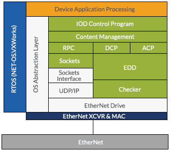
User Application (orange)
The user application “plugs” the modules into the slots on power on, starts the PROFINET task, generates diagnostic data, issues and releases alarms and maps the I/O data between physical device I/O and PROFINET IO.
RTOS – Real Time OS (blue)
The Real Time Operating System performs task management. At the minimum, PROFINET IO runs in one task, there is the user application task and there is a data exchange task.
PROFINET IO (green)
The PROFINET IO kernel is the software provided by Profibus International to developers. This software must not be changed. It consists of the following major sub components:
- IO Control Program – The IOD exchanges I/O data with the application
- Context Manager – The CM creates and manages the application and communication relationships with Programmable Controllers and IO-Supervisors
- RPC (Remote Procedure Call) – The subsystem that manages acyclic communications messages that arrive over UDP. These messages are the Read/Write services.
- DCP – Discovery Protocol for identifying PROFINET devices
- ACP – Alarm Control Protocol for managing Alarm generation and release
- Sockets – Sockets implementation that supports the sending/receiving of UDP messages
- EDD – The Ethernet Device Driver provides services to send and receive Cyclic, Acyclic and Non-Real Time (NRT) messages
- CHECKER – The Checker provides Frame Management and routing services. Frames are routed to the EDD or the Sockets interface for processing.
Interface Modules (gray)
The Interface modules provide the interface between the PROFINET IO kernel and the RTOS. These are mostly standard RTOS components but some must be modified to support PROFINET IO operation. The OS Abstraction layer is the only one that is not at least partially provided by the RTOS vendor. The abstraction layer maps the OS calls of the PROFINET core to the OS calls of the RTOS and is specific to the RTOS. The abstraction layer is specific to an implementation of the RTOS.
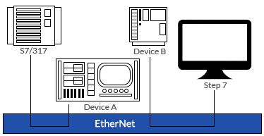
PROFINET Configuration Structure
PROFINET IO devices are typically configured by Siemens Step 7 software. Using Step 7, devices descriptions are loaded from the GSDML files. I/O configurations are mapped into the I/O tables of the Siemens IO Controller and IP addresses are assigned to each PROFINET IO device. The figure below graphically represents the structure of this system.
Where Does PROFIBUS Fit In?
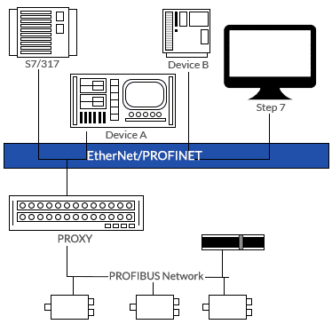
Profibus® is a worldwide standard for transmission of process data between field level devices and programmable controllers. How can I/O data and other information travel between Profibus and PROFINET IO? At the physical level these two communication networks are completely incompatible. Profibus is at its core an RS485-based communication standard with a maximum baud rate of 12M. At the core of PROFINET is Ethernet, another worldwide standard with baud rates of 100M and beyond.
Are they at all compatible at the protocol level? Profibus is I/O driven. Data is transferred as blocks of inputs and outputs which are interpreted by agreement between the Profibus Master and the Slave. PROFINET is also I/O driven with data transferred in blocks of inputs and outputs. In both systems, there is a Master or IO-Controller and one or more IO devices.
Since a Profibus Master device can access all the data of the Profibus network the logical place for a communications gateway is as the Master device of the Profibus network. This is illustrated in the figured below.
PROFINET CERTIFICATION
Unlike Profibus, all PROFINET IO devices must pass certification prior to product launch. The Certification Office of the Profibus User Organization is responsible for establishing test centers where PROFINET IO devices can be certified. The first PROFINET IO test center is located in Germany . A US Test Center opened in 2005.
Certification of a PROFINET IO device is a three step process:
- Runtime Software Certification – All the runtime interfaces are tested for compliance with the PROFINET IO specification.
- Engineering Model Certification – The PROFINET IO device is tested for compliance with an Engineering tool.
- Field Compliance – The PROFINET IO device is tested in a network of PROFINET IO devices to verify compliance in a field environment.
- PROFINET IO certification generally takes up to 8 weeks from commencement. One working device must be presented to the Test Center which maintains strict confidentiality.
How to Get Started
The PROFINET Runtime Core software can be downloaded free of charge (membership required) from Profibus International as a zip file. Porting PROFINET to a specific RTOS requires the developer to port each PROFINET component. The components to port include the RPC, Context Manager, Sockets Interface, Discovery Protocol, Alarm Handler Interface and the Ethernet Device Driver. The PROFINET Integration manual provides individual instructions for the porting of each of these components.
Prior to starting this effort the developer should have a background in the Microsoft RPC, COM, Sockets and C++. An extensive background in the specific operation of your RTOS, the operation of your TCP/IP stack and the fundamentals of your processor are also important.
PROFINET implementation is not without challenges. Porting of your PROFINET core to your embedded RTOS is a significant challenge. The PROFINET core is designed for Net OS from NetSilicon. Other cores may be available.