
An Introduction to
DeviceNet
DeviceNet™ Unplugged – A View “Under the Hood” for End Users
DEVICENET SYNOPSIS
This paper presents an operational description of DeviceNet™, a low-level industrial application layer protocol for industrial automation applications. DeviceNet connects simple industrial devices (sensors and actuators) with higher-level devices such as Programmable Controllers. Built on the standard CAN (Controller Area Network) physical communications standard DeviceNet uses CAN hardware to define an application layer protocol that structures the task of configuring, accessing and controlling industrial automation devices.
This paper is intended for the DeviceNet user who desires a deeper understanding of DeviceNet. It is intended to provide much more information than is typically found in a DeviceNet network overview but much less than the several hundred page DeviceNet specification. This paper can also provide a starting point for developers considering adding DeviceNet communications to their product.
Note that an abstract of a 200+ page specification is by definition incomplete. Some aspects of the technology are admittedly only lightly covered while others are not covered at all. Topics judged to provide the most insight into DeviceNet operation or clear up common misconceptions received priority.
DeviceNet – A Quick Overview
DeviceNet is an application layer protocol. What does that mean? One way to look at it is that the term “Application Layer” implies that DeviceNet deals more with application data than a lower level or non-application layer protocol. For example, a link layer protocol is designed simply to move some bytes from point A to point B. It has no interest and conveys no inherent information regarding the contents of the message. Because DeviceNet is an application layer protocol its messages do convey information. A DeviceNet explicit message has specific information in specific bytes of a message. There is a byte for a Class number, a byte for a service code and so on.
Now, if DeviceNet is an application layer protocol, what are the lower protocol layers that transport its messages? That’s the content of the next section.
DeviceNet and CAN
Controller Area Networking or CAN is a communications standard with a rather prolific set of offspring that includes DeviceNet, Can Open, Can Kingdom and several hundred other offspring all over the world.
Controller Area Networking is a serial communications standard for intelligent devices to communicate with each other. Unlike many other communication standards that provide fast data rates with thousands or millions of data bytes in a single frame, CAN has a bit rate that max’s out at 1 mega baud. Most industrial applications don’t even need that speed. Most use the lowly 125Kbaud. And where other standards move thousands of bytes in a single frame CAN only moves 8 bytes of data.
But where speed and capacity are strengths for many of the other standards, CAN’s strength is its low overhead and simple physical interface. With its small packet size, even at 500Kbaud a frame with eight bytes of data is only on the network wire for a quarter of a millisecond. For many control applications this is plenty fast.
Additionally the microcontroller, yes an underpowered 8-bit micro can get the job done, needs as little as 4K of program memory and 256 bytes of RAM to support a CAN application.
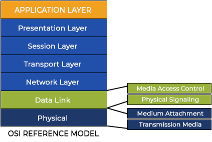
CAN was created by Bosch in Germany in March of 1985. The Bosch Company designed it to replace automotive wiring. In the early days of specification version 1.2, CAN messages contained an eleven-bit identifier providing the capability to address 2047 identifiers. In 1992 CAN Specification 2.0 extended the identifier size to 29 bits providing up to 56 million unique identifiers. As both specifications are still in use (sometimes on the same wire) the original 1.2 specification is called Part A and the new specification 2.0 is termed part B. A unique attribute of CAN is that only two of the OSI Reference Model layers are defined (Figure 1), the Data Link Layer and the Physical Layer. The CAN Data Linker is normally split into two sub layers, the Physical Signaling sub-layer and the Media Access Control (MAC) sub-layer.
Allen-Bradley (Rockwell Automation) created DeviceNet as an application layer protocol on top of CAN in the 1990’s. AB selected CAN as the DeviceNet Physical Layer for a number of reasons including:
- An extremely robust physical layer
- Open Technology
- Small processor footprint (RAM, ROM Requirements)
- Inexpensive physical components with multiple sources
One of the most extraordinary features of CAN (and DeviceNet) is bitwise arbitration. Bitwise Arbitration is the process that CAN uses to prioritize messages without losing any network bandwidth. On a CAN network “zero” bits dominate “one” bits. As a device transmits a message it listens to the bits on the network. If a device transmits a one and hears a zero, it knows that a higher priority message is being transmitted and it discontinues transmitting. The node with the higher priority message hears the bits it is transmitting and never knows it conflicted with a lower priority message. The message sequence on the network is preserved.
DeviceNet and CIP
The Communications and Information Protocol (CIP) is a communications protocol for transferring automation data between two devices. DeviceNet is a combination of the CIP Protocol and the CAN Physical Layer. In the CIP Protocol, every network device represents itself as a series of objects. Each object is simply a grouping of the related data values in a device. For example, every CIP device is required to make an Identity object available to the network. The identity object contains related identity data values called attributes. Attributes for the identity object include the vendor ID, date of manufacture, device serial number and other identity data. CIP does not specify at all how this object data is implemented, only what data values, usually called attributes, must be supported and that these attributes must be available to other CIP devices. The Identity object is an example of a required object. There are several types of objects defined by the CIP protocol:
REQUIRED OBJECTS
Required objects are required by the specification to be included in every CIP device. These objects include the Identity object, a Message Router object and a Network object.
IDENTITY OBJECT
The identity object contains attributes that identity the DeviceNet device. Attributes for the identity object include the vendor ID, date of manufacturer, device serial number and other identity data.
MESSAGE ROUTER OBJECT
The Message Router is an object that exists to route explicit messages and explicit responses to and from the Connection Object. For example, an Explicit Message request is received by the Connection Object and passed to the Router Object. The Router opens the DeviceNet (CIP) package and identifies the target object. The message is passed to the target object for processing. Response from the target object follow the identical course in reverse. Remember that this is only the external operating behavior of the Message Router Object. The implementation of this object can and does follow a much more concise and efficient mechanism.
DEVICENET OBJECT
The DeviceNet object contains attributes that identify the Port, Baud Rate, Mac ID (DeviceNet Address), vendor ID and other physical operating parameters.
CONNECTION OBJECT
The Connection object contains the attributes that control the processing of explicit and I/O messages. Most importantly, the attributes for the I/O Path and Connection Type control how often the DeviceNet devices produces data and the path where the connection object “finds” the data to produce.
Another required object is the Message Router Object. The DeviceNet specification describes these objects in excruciating detail.
APPLICATION OBJECTS
Application objects are the objects that define the data encapsulated by the device. These objects are specific to the device type and function. For example, a Motor object on a Drive System has attributes describing the frequency, current rating and motor size. An Analog Input object on an I/O device has attributes that define the type, resolution and current value for the analog input.
These application layer objects are predefined for a large number of common device types. All CIP devices with the same device type (Drive Systems, Motion Control, Valve Transducer…etc) must contain the identical series of application objects. The series of application objects for a particular device type is known as the device profile. A large number of profiles for many device types have been defined. Supporting a device profile allows a user to easily understand and switch from a vendor of one device type to another vendor with that same device type.
A device vendor can also group Application Layer Objects into assembly objects. These super objects contain attributes of one or more Application Layer Objects. Assembly objects form a convenient package for transporting data between devices. For example, a vendor of a Temperature Controller with multiple temperature loops may define assemblies for each of the temperature loops and an assembly with data from both temperature loops. The user can than pick the assembly that is most suited for the application and how often to access each assembly. For example, one temperature assembly may be configured to report every time it changes state while the second may be configured to report every one-second regardless of a change in state.
Assemblies are usually predefined by the vendor but CIP also defines a mechanism in which the user can dynamically create an assembly from application layer object attributes. Dynamic assemblies are rather rare, as most end users wouldn’t want to bother defining their own assemblies.
VENDOR SPECIFIC OBJECTS
Objects not found in the profile for a device class are termed Vendor Specific. The vendor includes these objects as additional features of the device. The CIP protocol provides access to these vendor extension objects in exactly the same method as either application or required objects. This data is strictly of the vendors choosing and is organized in whatever method makes sense to the device vendor.
In addition to specifying how device data is represented to the network, the CIP protocol specifies a number of different ways in which that data can be accessed such as cyclic, polled and change-of-state.
Connections and Connection IDs
DeviceNet is a connection-based network similar to Ethernet’s TCP/IP. When two devices establish a connection they exchange Connection ID Numbers. For most DeviceNet Messaging, messaging between a Master Device and a Slave device, the Connection IDs are predefined enabling low resource devices to optimize processing of these messages. Using the filters provided in a lot of CAN controllers, these messages are easily identified and processed while all other messages are quickly discarded.
For all but a few types of connections, two connection IDs are allocated. One, the produced Connection ID is allocated for the message transmitted by the device. The second is the consumed Connection ID, the Connection ID used in the message consumed by the device.
The Connection IDs are an integral part of DeviceNet messaging and are a part of the message prioritization scheme. The CAN Identifier in every DeviceNet message is composed in part of the DeviceNet Address and the Connection ID for the message. The lower the Connection ID/DeviceNet address combination the higher the priority of the message on the network. In some networks with certain types of messaging schemes using lower Mac ID addresses for higher priority devices is a valid optimization strategy.
Unconnected Message Connections
Every DeviceNet device contains a special virtual access port called the Unconnected Message Port. This virtual port provides a way for a device to send a few predefined messages to a DeviceNet device without first making a connection. The predefined messages are limited to creating and deleting other connections.
The Unconnected Message Port is part of the Group 2 Connection Set, the set of connections used by DeviceNet Slave devices. This connection is designed for very unsophisticated, low resource devices. In fact this connection set is exactly how a DeviceNet Master allocates a DeviceNet Slave, by sending messages on the Group 2 Unconnected Message Port.
More sophisticated devices also implement the Unconnected Message Port. For these devices this port can be used to create Explicit Connections on Connection Groups 1 or 3, connection groups that are used to transfer Explicit Message Requests.
Connected Message Connections
Connected Messages are messages produced and consumed across a connection between two devices. Connected messages can be either Explicit Response/Request type messages or I/O messages containing formatted data. Connected messages can also be messages transferred at some specific data rate (cyclic messages), on response to a poll (poll response messages) or on a Change-Of-State (COS messages). The data may be public, predefined assemblies of data or proprietary data specific to a particular vendor (proprietary peer message). The fact that two devices are connected does not imply anything about the data being transferred over the connection.
The Master Slave Connected Messaging
DeviceNet devices can be classified as Master or Slave devices. Master devices are devices that gather Input data from multiple slave devices and distribute Output data to the slave devices. Master devices are also referred to as Scanners and Client devices while slaves can be referred to as Servers. Master and Slave devices use a set of connections and message sequences that are termed the “Master Slave Connection” Set. This set of connections and messages provides a convenient way for DeviceNet Master device to Allocated, Configure and transfer I/O data to an unsophisticated DeviceNet Slave.
The Predefined Master Slave Connection Set is described in great detail later in this document.
I/O Connection Messaging
I/O Connections are connections that distribute Output data to DeviceNet Slaves and gather Input data from DeviceNet Slaves. The direction of data transfer is always discussed in terms of the DeviceNet network. Data that is moved from the network into a device is Output data. Data that is moved from a device to the DeviceNet network is Input data.
I/O Connections for the Predefined Master/Slave Connection Set are discussed in detail later in this document.
Offline Connection Messaging
DeviceNet now includes a connection set for devices in the Communication Faulted State. A DeviceNet device is Communication Faulted if on power up it detects another device with the same MAC ID (DeviceNet Address). A device in the Communication Faulted state is unable to transfer any data or perform any application operations until the fault is cleared. The fault is typically cleared by manually re-addressing the network so that no devices exist with duplicate addresses.
If many devices have the identical address, manually re-addressing the network is very time consuming and difficult. Either the switches on the device must be individually and manually changed or all devices must be removed from the network. Once all devices are removed each software addressable device can be added to the network and re-addressed one at a time by a configuration tool.
This time consuming and tedious procedure is what the Offline Connection Set messaging is designed to address. Using the Offline connection set a configuration tool can connect to a Communication Faulted device, change its address and then reset it. Since many Communication Faulted devices may be sharing an address, the configuration tool uses the vendor serial number to identify a specific device on the network. By flashing the LEDs of that device in a specific patter, the tool can identify the faulted device to the user who then can assign an address to that device.
Unfortunately only a minority of devices support the Offline Connection Set.
DeviceNet Messaging
There are three kinds of messages that can be transmitted between DeviceNet nodes. Peer messages are unformatted messages between any two nodes. Explicit messages are Request/Response type messages from a DeviceNet Master to a DeviceNet slave that Get or Set an attribute in a DeviceNet Object. I/O Messages are messages that transfer predefined I/O data between a DeviceNet Master and a DeviceNet Slave.
Peer Messaging
Peer Messaging in DeviceNet is a widely misunderstood concept. Though Peer Messaging is supported there is no practical way for devices manufactured by different vendors to communicate over peer communication channels.
Peer messaging is simply the exchange of messages from one DeviceNet device to another over any non-Master Slave connection. If two devices both support unconnected messaging and one of the devices can issue an unconnected message a peer communication channel can be created between the two devices.
Unfortunately creation of the peer communication channel does not imply that the two devices can exchange meaningful data. Unlike the Group 2 Only communication set (Master/Slave), there is no well-defined rule or organization for the data exchanged on Peer Communication channel. If a DeviceNet temperature controller sends a temperature over a peer connection to a display, there is no way for the display to decipher the data. The temperature may be in Celsius or Fahrenheit. It may be 16 bits or 32 bits, scaled or un-scaled. Unlike an I/O message between a DeviceNet Master and a Slave, there is no implied structure or meaning to the bytes sent on a peer communication channel.
Most implementations of Peer communications are used by devices manufactured by the same vendor. The vendor defines the format and contents of the message so that each device can understand the contents of the message. Barcode vendors sometimes use peer messaging to create what is called a “poor man’s universal scanner. Using 2 or more scanners situated all around a target the barcode device which reads the barcode sends a message to the other scanners indicating that it has the barcode and that they can discontinue scanning.
Explicit Messaging
Explicit Messages are request/response messages that are issued by a DeviceNet Master to request a service from a DeviceNet Slave over an Explicit Message Connection. The Service Code field in the explicit message identifies the requested service with the remainder of the message containing any data required to execute the service. The GET_ATTRIBUTE Service Code is a typical request carried in an Explicit Message. GET_ATTRIBUTE returns the value of an attribute to the device issuing the Explicit Message. Explicit messages are used by all devices including configuration tools.
I/O Messaging
I/O Messages transfer predefined I/O data between a DeviceNet scanner and an I/O device. Traditionally Inputs and Outputs are referenced from the point of view of the network. An input is a data point produced by an I/O device and transferred to a scanner over the network. An output is a data point consumed by an I/O device and transferred from a scanner to a device over the DeviceNet network.
I/O data is contained in a device in one or more device assemblies. The Input Assembly Object identifies the data produced by the Device. Attribute three of each Input Assembly object is the attribute containing the data to produce. Attribute three is usually a collection of data from one or more application objects. Figure 2 is an example of the Assemblies that you might find in a simple flow meter.
Output Assembly objects identify data consumed by the device. Attribute three of each Output Assembly identifies the specific data consumed by the device. Attribute three of each Output Assembly is usually a collection of data consumed by the device. The data consumed is destined for one or more application objects as it is received.
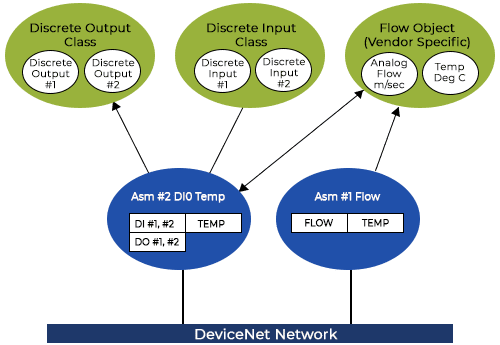
A device can have multiple Input and Output Assemblies. For example a barcode reader device may have some set of discrete inputs and outputs. The assembly objects for the barcode device may include an assembly with only barcode data, an assembly with just I/O data or an assembly that contains both barcode and I/O data. This provides the ultimate flexibility for the end user. An end user that doesn’t use the I/O on the barcode reader selects the first assembly. A user who is using the barcode reader as a discrete I/O device might select the second assembly while the user using both may select the last assembly.
Figure 2 is an example of a device with more than one assembly. In this example, the user can choose from two assemblies for a simple Flow Meter. Assembly #1 contains the flow and temperature while Assembly #2 contains the Discrete I/O data.
In these cases the I/O connection must be configured to reference an assembly other than the default assembly. In the Connection object there are a minimum of two connection instances. One instance is for the Explicit connection and one instance for the I/O connection. The Explicit connection describes the how explicit messages are transferred. The I/O connection descries how messaging is managed.
The Connection Path attribute in the I/O connection is the Assembly Object containing the data to consume and produce. There are a number of different ways to specify the connection path most of which require more explanation than can be provided in this document.
To change the Connection path a user can use an Explicit message to set this path directly or in many cases the vendor of the device provides a selector attribute in one of the application objects to more easily set the path. If a device only supports direct management of the Connection Path attribute the user may have to consult the device documentation or the DeviceNet specification to correctly specify the path.
I/O messages come in a number of flavors:
- POLLED – Polled messages are request/reply messages issued to the polled connection. Polled messages are sent by the scanner at the rate of its choosing.
- CYCLIC – Cyclic messaging is scheduled messaging. In this mode the DeviceNet Slave device periodically issues messages to the Master at some scheduled rate.
- Change Of State (COS) – COS messages are messages which are produced on the I/O connection on an event. Additionally, a heart beat message is also issued by the DeviceNet slave device. The heartbeat lets the scanner know that the slave device is still alive.
All messages transfer an I/O Assembly between the Scanner and the Adapter. Scanner and Adapter are alternate terms used by some DeviceNet folks to refer to the DeviceNet Master (scanner) and Slave (Adapter). I/O messages also implement a fragmentation scheme for I/O data greater than the CAN Standard 8 data bytes. Unlike the fragmentation protocol used for Explicit Messages, fragmentation for I/O Messages is not acknowledged and not sequenced. The multiple messages are transmitted with no special encoding or sequence number. The receiver simply reconstructs the I/O data in the order that the messages are received.
DeviceNet Synopsis
GET and SET Attribute Service codes are the most common messages carried by Explicit Messages. Service Code data associated with these messages includes:
- Object Class – The Object Class Number of the Object in the target device
- Instance Number – The specific occurrence of the Object Class in the target device. For example, a device with 16 Input Points may be implemented with one Input Object with 16 instances, one for every input point.
- Attribute ID – The index to the specific value in the object being addressed by the Get or Set Attribute service
- Attribute Value (Set Only) – The new value for the attribute
A Get Service request to obtain the device Serial Number looks like this:
| Connection ID | Service Code | Object Class | Instance | Atrribute ID |
| —–CID—– | OE Hex | 1 | 1 | 6 |
All Explicit messages are routed through the Explicit Message Router inside the DeviceNet device. The Router validates the Object Class. If the Explicit Message contains an invalid Class, the router rejects the message and returns an error code to the requester. If the Router validates the Object Class it passes it to the target Object for processing. The response from the target object is returned to the requester through the router. Note that this is only the network view of the device operation and may or may not be how the device is implemented.
One interesting application of Explicit Messages is that they can be used to read I/O data. An Explicit Message can be formed to get the attribute data containing the I/O data. The I/O data can be retrieved from either the source object generating the data or the assembly object containing the data ready to transfer to the Master.
An Explicit Message connection may support a fragmentation mechanism for messages greater than 8 bytes. Fragmented explicit Messages contain only six bytes of data. Two header bytes to manage the fragmentation are added to every message. One header byte indicates the fragmented message position (First, Last, Middle) in the message sequence while the second byte contains a sequence number.
Unlike I/O Message Fragmentation, Explicit Messages must be acknowledged. The receiver (Master or Slave device) must transmit a message indicating acceptance of the fragmented message before the next message in the sequence is transmitted.
DeviceNet devices are not required to support Explicit Message fragmentation. In fact most devices do not as Explicit Message fragmentation and the required acknowledgement handing requires a tremendous amount of device resources. A little know fact is that most DeviceNet device names (an ASCII string) are eight or less bytes in length to avoid support of explicit message fragmentation since longer product names would be transferred to the Master as a fragmented message sequence.
Connection Establishment Messaging
There are only two requirements for successfully placing a new device on a network. One, the baud rate of the device much match the baud rate of all other devices on the network and two, the device address must not conflict with an address of another device.
BAUD RATE
There are three baud rates for DeviceNet networks; 125K, 250K and 500K . The baud rate limits the length of the network. Very simply, CAN networks require every device to listen to its own bits as they are transmitted and to set the acknowledge bit in each and every message transmitted on the network. The implementation of this latter requirement dictates the maximum network length for each baud rate:
| Date Rate | Trunk Length |
| 125K | 500 Meters (1640 feet) |
| 250K | 250 Meters (820 feet) |
| 500K | 100 Meters (328 feet) |
Identifying the current baud rate of a device can be a challenge. Unless a device is configured using dipswitches and the baud rate can be discerned from the switches, there is no way to know what the baud rate might be. One of the reasons that a device may not connect is a baud rate that is different than the network baud rate. If you don’t know the baud rate of a DeviceNet device the only sure method to find out is to try to connect to it at each baud rate.
DeviceNet Address
An integer address is assigned to every DeviceNet device on a network. This integer is the device address or MacID. MacID is short for Media Access Identifier. There are a maximum of 64 nodes on a DeviceNet network. These nodes occupy MacIDs (addresses) 0 to 63 and can be set using switches or using a DeviceNet configuration tool. No two devices can occupy the same DeviceNet Address.
At power on each DeviceNet device sends out a message requesting access to the network. Part of this message is the unique device serial number. If more than one devic from the same vendor all with the same vendor id power on and attempt to access the network at the identical instant the device with the lowest DeviceNet serial number is successful. All the other devices fault. This sequence is explained in more detail in the next section.
Duplicate MAC ID Sequence
The DeviceNet protocol requires that devices transitioning from the offline to on-line state follow a very specific message sequence with specific timing. This sequence relies on the Duplicate MacID request message. This message consists of the devices Vendor ID and Serial Number. The Vendor ID is the integer ID assigned to the vendor by the ODVA while the serial number is a unique long integer assigned by the vendor. Since the vendor is required to assign a unique serial number to each device no two DeviceNet devices anywhere on the planet can have the same vendor/sequence number combination. This ensures that no two Duplicate MacID request messages can have the same contents. If two devices from the same vendor attempt access to the network at the same instant during the Duplicate MacID sequence the device with the lowest vendor/sequence number combination will get access first.
The Duplicate MacID sequence consists of sending two consecutive Duplicate MacID request messages with a one second delay between messages. During the delay any online device with the same MacID must issue a Duplicate MacID Response Message. If the device joining the network receives a Duplicate MacID Response Message it transitions to the Communication Fault state. If no response is received after the second, one second delay, the device can officially transition to the online state.
There are other more subtle requirements for DeviceNet devices. For example if a device in the online state ever receives a Duplicate MacID response message it must immediately transition to the offline state. Receiving a Duplicate MacID response indicates that there is another device on the network in the online state with the same MacID.
Miscellaneous Messages
A message that is directly opposite the Duplicate MacID request message is the device shutdown message. This message broadcasts the fact that a device is transitioning from the online state to the offline or non-existent state. This is an optional message that can be used by a device to signal a fault condition, remote command or some other reason for taking itself off the network.
Another infrequently used message is the Device Heartbeat message. Devices that support Change-Of-State (COS) operation use the Device Heartbeat (DHB) message to communicate to the Master that they are operational. If no COS message containing new data is produced for a set duration the device produces the DHB message.
Error States
DeviceNet devices can assume any of the following state:
| NON-EXISTANT | The device has shutdown due to an internal error or some remote command. |
| UNALLOCATED | The device has successfully joined the network but is not currently “owned” by a DeviceNet Master device. The LED Network Status indicator for an unallocated device flashes green. |
| TIMED OUT | Messages have failed to arrive on one or more connections with the Master device. This is typically a recoverable error. The Network Status LED indicator on a device will typically flash green in this state. |
| FAULTED | The device has detected an internal error or received a Duplicate MacID response message. This is not a recoverable error. The Network Status LED indicator on a device will typically be solid red in this state. |
| BUSOFF | In the BusOff state the device has detected significant network errors and has removed itself from network operation. This is typically a hardware failure in the device circuitry. The Network Status LED will typically be solid red in this state. |
DeviceNet Device Types
There are three basic DeviceNet device types; Master Devices, Slave Devices and Peer Devices. A device can support any one or all of the device types simultaneously.
Master Devices (Scanners)
Master Devices, sometimes known as Scanners but not usually as Client devices, are devices that “own” DeviceNet Slave Devices. A Master can own many or all the Slave devices but a slave can only be “owned” by one DeviceNet Master at a time.
A Master device must first “allocate” a DeviceNet Slave device to obtain ownership. The allocation process, described later in this document, is a set of handshaking messages in which the Master device requests control of the slave and then configures the slave to transfer a particular set of data at a data rate specified by the Master. The typical set of messages that request ownership is known as the “Predefined Master Slave Connection Set”.
The Allocation process is simply an Open Explicit Request message issued on the Unconnected Message Port requesting ownership of the Slave device. If the slave accepts ownership it replies in the affirmative and creates the connections requested by the Master Device in the request message. Usually the Master requests both an explicit and an I/O connection.
A Slave may deny the allocation request from the Master Device. Slaves may deny a request if they are already allocated to another Master or if the Master device requests an unsupported connection type. For example if the Master requests a cyclic connection and the DeviceNet Slave only supports polled connections the allocation request is denied.
Once the Slave accepts the connection request the Master uses the Explicit Message connection to configure the I/O connection. Configuration includes setting the two most important attributes of the I/O connection; the Expected Packet Rate and the produced and consumed connection paths. The Expected Packet Rate is the rate at which the Master expects to scan the DeviceNet Slave device. If the Master fails to scan at this rate, the Slave device enters a Timed-Out state and must be explicitly reactivated by the Master Device. The Produced and Consumed connection paths are the paths to the application objects where data is respectively generated or stored. Generally these paths refer to one of the assemblies supported by the Slave device.
Scanning can begin once the Slave device is fully configured. During scanning the Master device produces and consumes Slave data. The Master produces data for the Slave’s Output Assembly that is identified by the Consumed Connection path in the Slave. The Master consumes data generated from the Slave’s Input Assembly that is identified by the Produced Connection path in the Slave’s Output Assembly.
Slave Devices (Adapters)
Slave Devices, sometimes known as servers, are devices that receive and transmit application specific data to and from a Master device. Slave devices by definition implement the Predefined Master Slave Connection Set described in the previous section.
Slave devices must support at least one or more of the following I/O Message transport types:
- POLLING – In this operation mode the Master device transmits I/O data to the slave device at some rate. This rate must be greater than the rate specified by the Expected Packet Rate when the connection was configured. The Slave device responds to a polling message by producing the data in its input assembly.
- CYCLIC – In Cyclic Messaging the Master device transmits I/O data to the Slave device at some rate. This rate must be greater than the rate specified by the Expected Packet Rate when the connection was configured. The Slave device may or may not be configured to respond immediately. In the typical situation, the Slave device produces its I/O data at a frequency configured by the Master device.
- CHANGE-OF-STATE (COS) – In COS Messaging the Master device transmits I/O data to the Slave device at some scan rate greater than specified in the Expected Packet Rate. The Slave device may or may not be configured to respond immediately. In the typical situation, the Slave device produces its I/O data ONLY when the application layer indicates data has changed or upon expiration of some transmission timer also known as a heartbeat timer.
A Master device implicitly transmits its current operating mode with every I/O scan. If the Master device (typically a Programmable Controller) is in a non-run mode the Master produces an I/O message with zero data bytes known as an IDLE mode message. The Slave device can then implement whatever functionality is required of the device when its master is not in run mode. Messages received with at least a single byte of I/O data indicate to the Slave device that the Master is now in Run mode. DeviceNet does not require a slave device to implement any specific behavior when a Master device is in an IDLE mode.
Master devices such as Configuration tools often allocate the Predefined Connection Set of a Slave device requesting only the Explicit Message request connection. These devices typically allocate the EM connection, get or set a particular attribute and then release the connection set. If these devices are currently allocated by another Master device the Master owning the DeviceNet slave mimics the messages of an unconnected slave device but only accepts the Explicit Message connection. Messages for the owned slave are received by this Master and sent to the slave. The response from the slave is received and relayed to the original requestor, just as if the original Master device was communicating with the Slave directly. In this fashion a device, like a configuration tool, can get or set an attribute of a DeviceNet slave even if a Master already owns it device.
Master Allocation Sequence
A Master DeviceNet device makes a connection with a slave device using the following sequence:
- The Master issues an Unconnected Open Request Message to the DeviceNet Slave. A DeviceNet slave device that supports unconnected messages allocates an explicit message connection and answer the Masters Message. The slave returns a connection id and describes the kind of messaging the slave can support. These Slaves then continue with step 6 of the message connection sequence.
- If a slave fails to answer the unconnected message request within one second the Master issues a second Unconnected Open Request Message. Slaves that don’t support unconnected messaging will ignore the Unconnected Open Request message.
- A slave may answer the second request, allocate an explicit message connection and return the connection ID to the master. These slaves than continue with step 6 of the message connection sequence.
- If a slave device fails to answer both Unconnected Message Requests the Master waits another second and issues a Group 2 Only Connection request. This message attempts an allocation of an explicit and/or IO connection using the Group 2 Only port. This is a special port designed only to support simple allocation of slave devices.
- Slaves that fail to answer the Group 2 Only Connect request are marked as faulted. Some Masters may retry the allocation sequence periodically but are under no requirements to do so.
- Using the explicit connection made in the previous step the Master uses the connection to configure the I/O connection. The Master sets the I/O timeout, connection paths and other attributes required to operate the I/O connection.
- Once the I/O connection is complete some Master will explicitly delete the explicit connection, as it is no longer needed.
Physical Media Issues
Indicators & Switches
DeviceNet devices are configured using external hardware or software configuration tools. External hardware can include rotary switches, thumbwheels, dipswitches and other fixed input devices. Software configuration tools access the internal configuration of the device over the DeviceNet network or other communication port. Generic tools that can configure any DeviceNet device use the DeviceNet network. Vendor specific tools that configure just the devices of that vendor may either use the DeviceNet network or some other communication port on a device.
Some end users prefer configuration using switches. Their philosophy is that a device can be easily replaced if all it takes is to set switches and connect the replacement devices. Other end users prefer software configuration. These users view switches as a potential source of device failure.
Termination
DeviceNet requires termination resistors at each end of a DeviceNet trunk line. One ¼ watt, 120 ohm resistor should be placed at each end of the trunk between the CAN-H and CAN-L signals. The DeviceNet specification expressly recommends that these termination resistors not be included within a device.
Isolation
Isolation of DeviceNet devices is recommended for devices with connections to external power supplies.
Electronic Data Sheets (EDS)
DeviceNet vendors are required to provide some type of documentation specifying how their device is configured. The document may be a set of printed instructions or some electronic file. At the minimum the vendor must provide instructions for any external switches and a list of Class/Instance/Attribute values that control the configuration of the device. Some vendors create a “configuration assembly” containing the parameter data. This assembly provides a single attribute, a single point of reference where all device parameters can be read and written.
An electronic listing of the Attributes that configure a DeviceNet device is usually provided by a vendor. These EDS files sometimes provide little to no information on the device or they can be very lengthy and complex. The more extensive EDS files allow configuration tools to precisely configure the device using text identifiers for bit values and other very informative text strings.
Typical DeviceNet Devices
DeviceNet I/O Devices
Most DeviceNet devices are Slave I/O devices. A DeviceNet I/O device transfers discrete or analog I/O points to a DeviceNet Master. DeviceNet I/O devices come in all shapes and sizes from one or two points to many points. A lot of I/O devices are non-isolated and are powered from the network while others use isolated outputs.
DeviceNet Masters
DeviceNet Master Devices are usually Programmable Controllers or Personal Computers. DeviceNet Master Devices allocated DeviceNet slaves and transfer data between the Master and its Slaves.
DeviceNet Gateways
DeviceNet Gateways convert data from another protocol to DeviceNet. Modbus DeviceNet gateways for example convert Modbus devices to DeviceNet devices. ASCII DeviceNet gateways take ASCII data and convert it to Modbus. There are innumerable protocol converters for DeviceNet.
The difficult issue for a DeviceNet gateway is mapping data in the other protocol to the object structure of DeviceNet. For example, the Modbus protocol represents its data as a series of 16-bit integers while CIP represents data as attributes that are part of objects. A DeviceNet gateway must allow some method to convert the data in its native Modbus, ASCII or other format to the object-based structure of DeviceNet.
DeviceNet Master Stack
A DeviceNet Master Software stack is the software the implements the DeviceNet and CIP Communication protocol. A DeviceNet Master must be able to send messages over the physical CAN network. To do that it must know the particular register interface of a selected CAN controller. A DeviceNet device developer that wants to implement a DeviceNet Master must create the interface between the DeviceNet Master and the CAN Controller selected by the hardware designer. Sometimes, as in the case of DeviceNet Master stacks provided by Real Time Automation, Inc., an interface file for a particular CAN Controller is delivered as part of the DeviceNet Master stack.
To implement a DeviceNet Master the application controls the DeviceNet devices to allocate, the number of data bytes to produce and consume and how often the DeviceNet slave devices are polled. For more information on implementing a DeviceNet Master application, contact Real Time Automation, Inc
DeviceNet Slave Stacks
A DeviceNet Slave Software stack is the software the implements the DeviceNet and CIP Communication protocol. A DeviceNet Slave must be able to receive an allocation message from a DeviceNet Master, consume outputs generated by the Master and produce inputs. To do that it must know the particular register interface of a selected CAN controller just like the DeviceNet Master stack. A DeviceNet device developer that wants to implement a DeviceNet Slave must create the interface between the DeviceNet Slave and the CAN Controller selected by the hardware designer. Sometimes, as in the case of DeviceNet Slave stacks provided by Real Time Automation, Inc., an interface file for a particular CAN Controller is delivered as part of the DeviceNet Slave stack.
To implement a DeviceNet Slave the application controls the DeviceNet address, the number of data bytes to produce and consume and the object structure of the device. Implementing the object structure of the device in the DeviceNet slave is one of the most important parts of implementing a DeviceNet slave device. This structure is the structure seen by the users of the device and must be implemented correctly to meet their needs.